LRE Gen-I | Engine Control System
Completion Date: June 1, 2022
The custom control system designed for our first-generation liquid rocket engine encompasses a large suite of electronics, firmware, and software that ensures the safe and successful ignition and operation of our propulsion systems.
At the heart of the system, power electronics supply and manage the electrical energy required for the engine's ignition and operations, while solenoid controllers regulate the flow of propellants by opening and closing valves at precise moments. The inclusion of advanced sensors allows for real-time monitoring of various engine parameters such as temperature, pressure, and flow rates, ensuring that the engine operates within safe and optimal conditions. Signal processing techniques are employed to analyze the data collected from sensors, enabling the identification of any anomalies or deviations from expected performance. This information is crucial for the computation units, which leverage sophisticated algorithms to make real-time decisions and adjustments to the engine's operations, ensuring its performance aligns with the mission's requirements. Furthermore, the system features robust communication capabilities, enabling seamless data exchange between the rocket engine and the control center. This connectivity allows ground-based engineers to monitor the engine's status in real-time, make necessary adjustments, and intervene if required, thereby enhancing the mission's overall safety and success rate.
This sophisticated control system integrates several interconnected components:
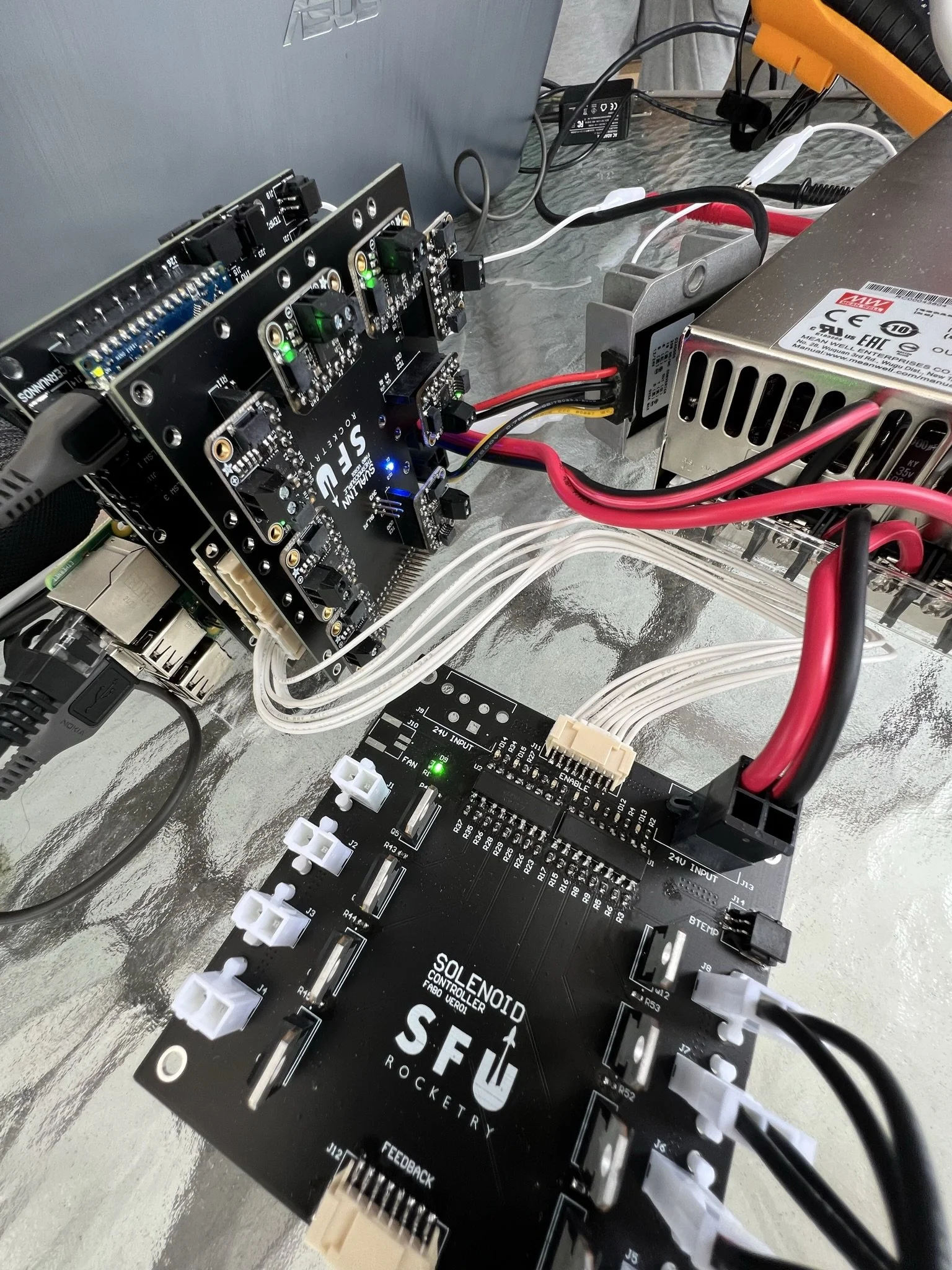
Power Conversion (PCB Alias: Cernunnos)
Our control system is a mixed bag of electronics, ranging from a bus of power-intensive solenoid valves to highly-sensitive current-feedback sensors, thus our ability to supply large amounts of low-noise power is critical.
Uses a customized synchronous buck converter topology to convert and smooth supplied power from either our AC gas-generator source or custom DC battery packs.
Supplies 500W at 24V with an acceptable 0.5% ripple and drop across its operational range.
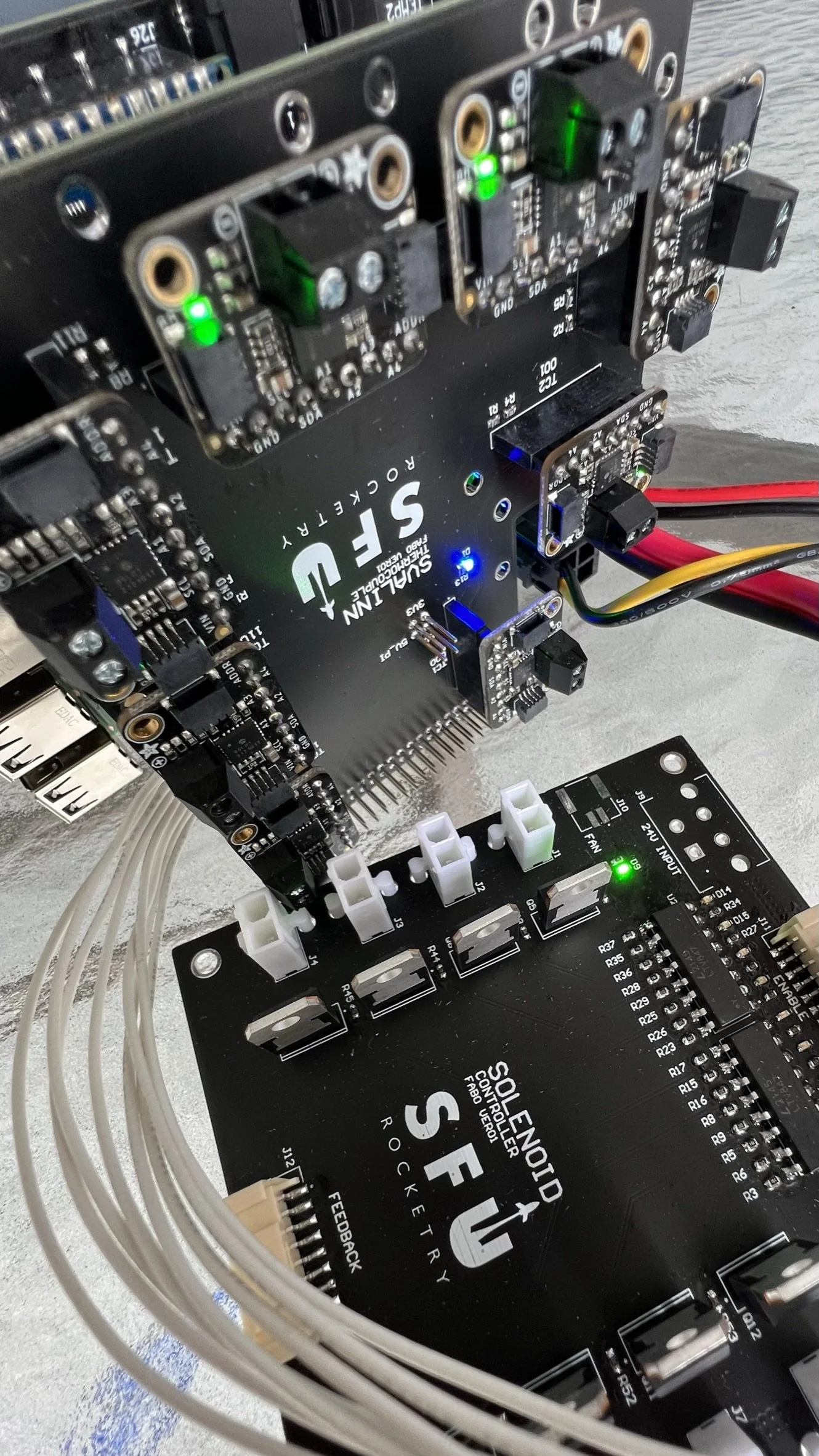
Solenoid Controllers (PCB Alias: SC)
The fluid system uses anywhere from 8 to 16 solenoid valves to control the flow of our propellants. These valves are either electrically or pneumatically controlled, either of which involves driving a solenoid.
Controller implemented as a solid-state system leveraging FETs and custom drivers made up of optoelectronic and digital latches. A solid-state approach was chosen as during an ignition the propulsion system experiences large vibrational forces, the electronics included. Relay bouncing from vibrations would present serious issues, and thus relays or other electromechanically actuated switches were not selected.
Uses custom driver electronics and a custom protocols to allow a large number of controllable solenoids with limited IO ports. Each controller can interface with up to 8 solenoids, and we have the ability to use multiple controllers in the system.
Includes failsafe redundancies to ensure all valves remain in a safe state upon power-loss or other complications.
Includes individual valve feedback to always remain aware of what state a valve is in, including error states such as a half-open or half-closed mode
Custom drivers give the ability to perform pulse modulation techniques to considerably save on power consumption.
Processing (PCB Alias: Svalinn)
Leverages a Raspberry Pi 3B+, this is inserted directly into our control system PCB stack.
Runs a custom Linux distribution and is ultimately responsible for relaying information between the control system and our mission command center, as well as rapidly scheduling the propulsion system sequence upon request for ignition.
Signal Pre-Conditioning (PCB Alias: Svalinn-SC)
With only 28 GPIO pins available, and a system of many serial interfaces, custom-protocol interfaces, individual control lines, and feedback sensors, we had to get creative with our IO network distribution.
Our comprehensive signal pre-conditioning network acts as the link between our Main/Master processor and Secondary/Slave peripherals, offloading computation from the processor and condensing communication busses.
Includes secondary microcontrollers, ADCs, latches, optoelectronics, multiplexers, and more.
Feedback Sensors (PCB Alias: Svalinn-PT)
Live-feed video allows us to monitor the system from a safe distance.
Inertial Measurement Units help us identify vibrational forces, and determine if the system is starting to shift or move, long before we could tell with our own eyes.
Limit Switches help us keep track of the state of hand-valves, eliminating the question “did I remember to close that valve?”
Pressure Transducers allow us to accurately pressurize our system.
Thermocouples allow us to measure combustion temperatures and cryogenic systems.
Flowmeters allow us to tune our propellent flow-rates during an ignition and burn sequence.
Force Gauges (Load Cells) allow us to measure our engine’s thrust output.
Failsafe Redundancies
Includes a watchdog that checks the processor is alive and well. Watchdog and processor handshake ultimately determines if the system state is considered “safe”.
All peripherals are on separately controllable power networks, allowing for complete control of each network and the ability to reboot/restart if lock-up issues ever occur.
All peripherals are designed to enter the best-possible safe state in the event of control or power loss, meaning the system can be safely approached after any complications occur.
The system makes decisions based on sensor feedback, power management status, and watchdog status to automatically change to a safe-state if an anomaly or concern is detected.